LED Screen Physical Setup ASB Display Boards
This article will explain how to physically set up a set of LED screen panels for use with display software that will create video output to a computer's desktop (such as AthleticSB, ResulTV or FT-Scoreboard).
Positioning and Interlocking
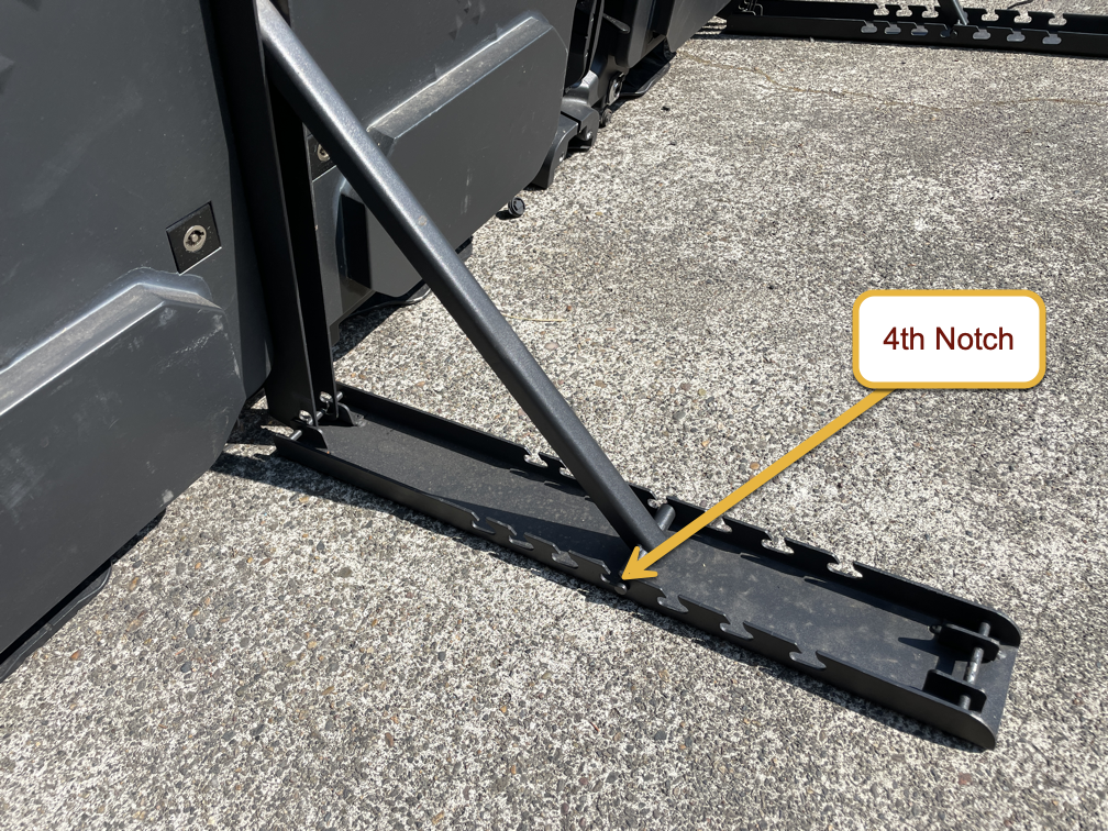
Position each panel in the desired location, and flip down the kickstand. For ground-level viewing, we recommend using either the third or fourth notch in the ground support leg.
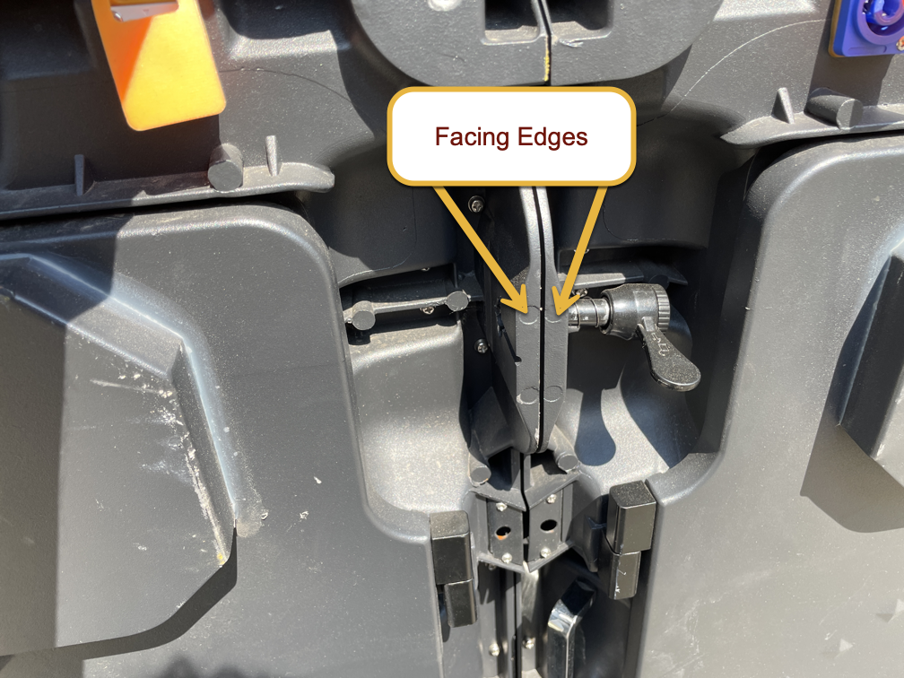
Position the panels close to each other, on a roughly level surface. The closer you can get the facing edges of each panel to each other, the easier locking them together will be.
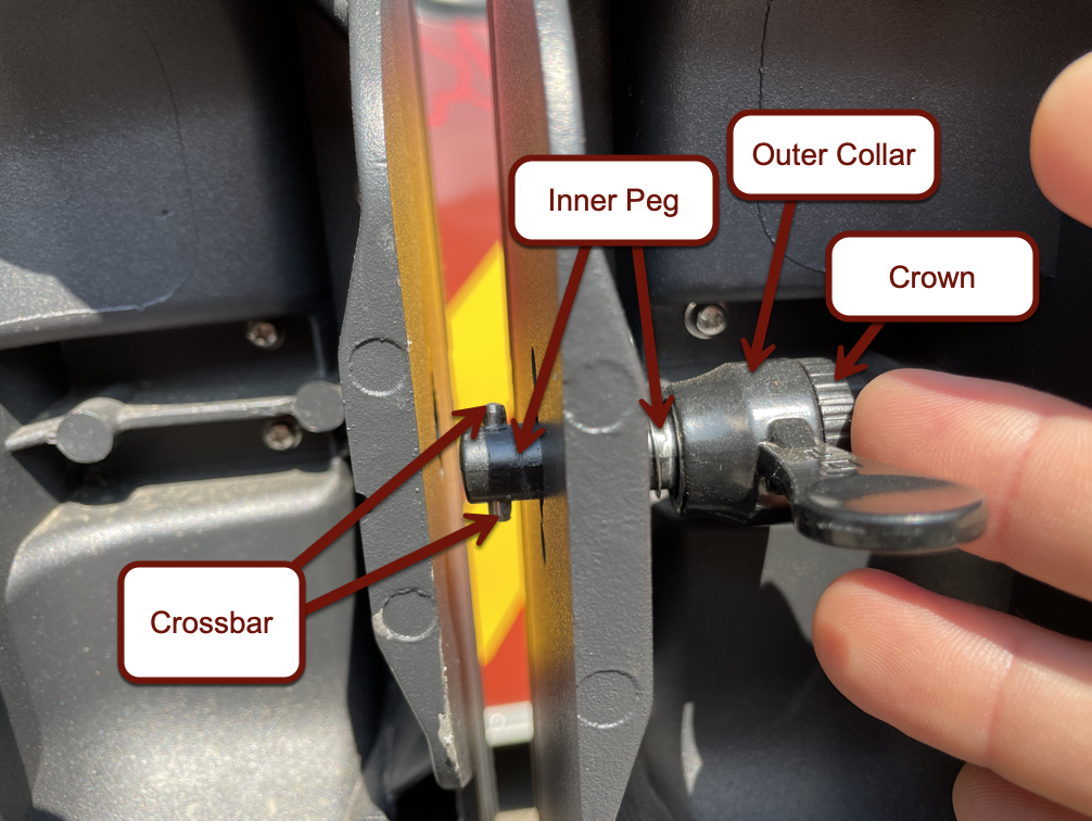
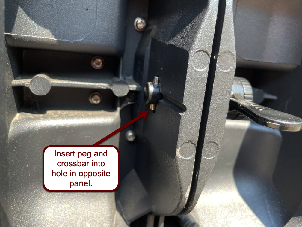
When facing the back of the panels, the right-hand panel will have lock pegs that lock into the left-hand panel. These lock pegs consist of two items: an internal peg with crossbar that locks into the corresponding hole in the opposite panel, and an outer collar with a lever to tighten the overall connection. The outer collar is threaded onto the inner peg.
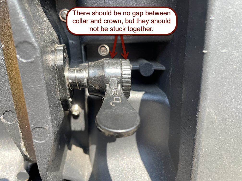
Before beginning to lock the panels together, ensure that no gap exists between the crown of the inner peg and the outer collar. Rotate the crown, if necessary, to eliminate this gap, but be sure that the two items will rotate freely and independently of one another.
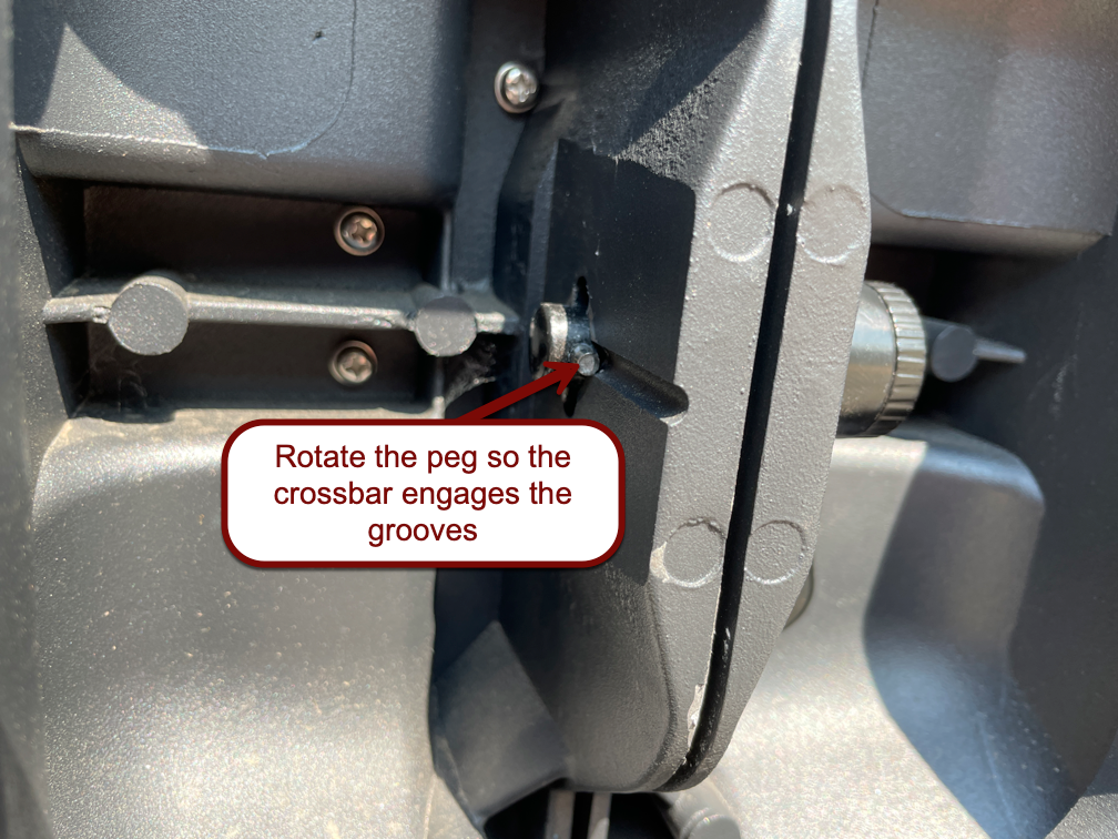
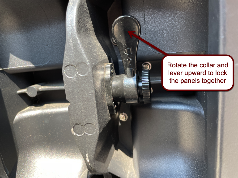
Insert the peg into the hole in the opposite panel. Ensure the crossbar is lined up with the corresponding notches in the hole so the peg gets fully inserted. Once the peg is fully inserted, turn the crown of the peg to rotate the crossbar 90º from how it was originally inserted, and then rotate the outer collar with the lever to lock the two panels together securely and eliminate the gap.
Power and Data Connections
Power Connections
The power connections are of the Neutrik PowerCon type. Each panel is equipped with a blue receptacle and a gray receptacle. Insert a cord with the corresponding connector color into the receptacle on the back of the panel and twist 90º clockwise to lock. To unlock, pull on the silver release tab before rotating 90º counterclockwise and removing.
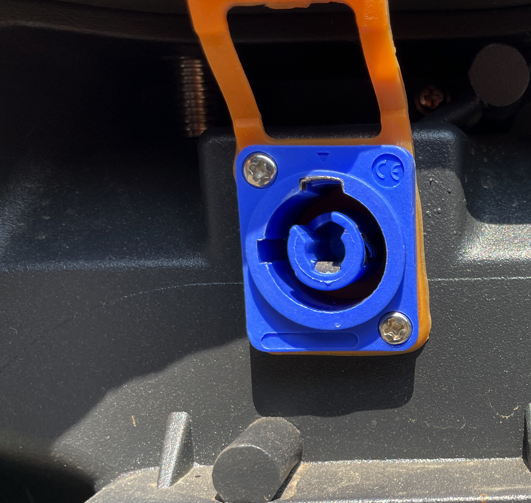
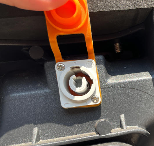
The blue and the gray connectors are not interchangeable. Blue ports and connectors are for electrical supply (power source), while gray connectors are for electrical drain (power output).
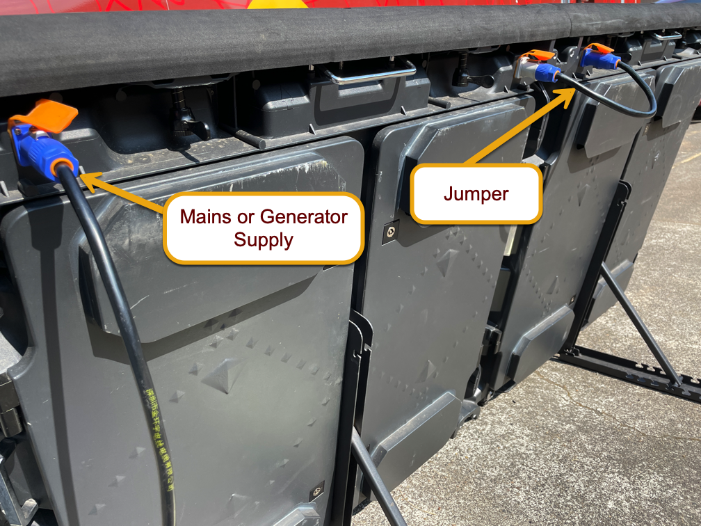
Your boards should come equipped with a long power cord with a standard wall plug on one end, and a blue PowerCon connector on the other, as well as a short jumper with a blue PowerCon connector on one end and a gray PowerCon connector on the other. The long power cord will supply electricity to your boards, and each jumper will allow you to power a subsequent board by creating a daisy chain.
Power consumption notes
LED screen cabinets are capable of consuming a great deal of electricity. How much electricity they consume is dictated by the brightness of what is being displayed on the screen. As an extreme example, a single panel, forced to display full white (maximum power consumption), can draw over 1900 watts (16 amps at standard North American wall voltage). To put that in perspective, that's as much electricity as two garbage disposals, and 400 more watts than your average portable space heater. Now, consider the fact that we don't normally run a single panel alone, but we're usually running two to four in tandem!
Thankfully, running every single pixel on a panel at full white is a very unlikely use case. Most scoreboard layouts have a significant amount of black on them, which consumes no electricity whatsoever. The point of providing this information is simply to illustrate the need for planning for a power source when running LED screens.
We've developed the following rule of thumb: No more than four display cabinets should be plugged into a standard 20-amp circuit. This will prevent you from having to track down where the circuit breaker is at whatever facility you happen to be at. We've also found that the “no-more-than-four” rule holds true when using a generator to power LED screens: a 2000-watt inverter generator will happily (if noisily) power four screens.
Data Connections
Screen data is fed from the sending card (attached to the control computer) to the LED screens by means of Cat-6 cabling. Data communications between individual LED screens is also accomplished through the use of Cat-6 cable and daisy-chaining.
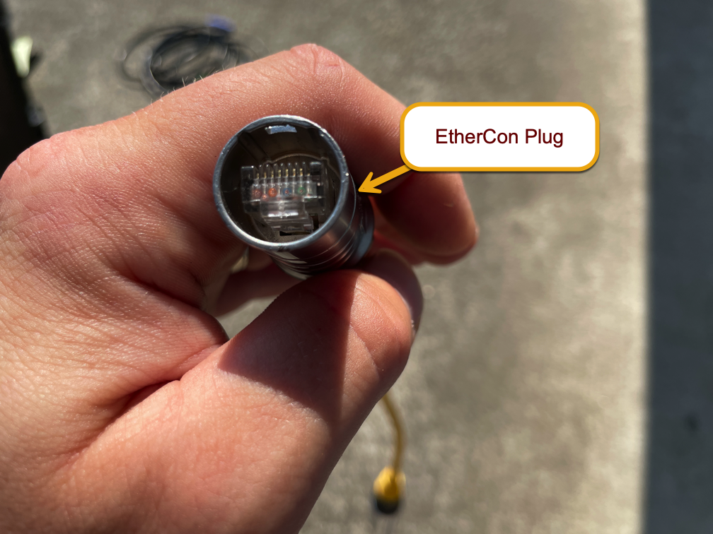
Each LED screen has a pair of Neutrik EtherCon receptacles—one at each bottom corner of the screen. These connectors can accommodate EtherCon connectors (which look like a standard RJ45 plug encased in a silver barrel similar to XLR) for a weather-resistant connection. Additionally, EtherCon receptacles can accommodate standard Cat-6 cabling, but you'll lose the weather-resistant properties of the connection.
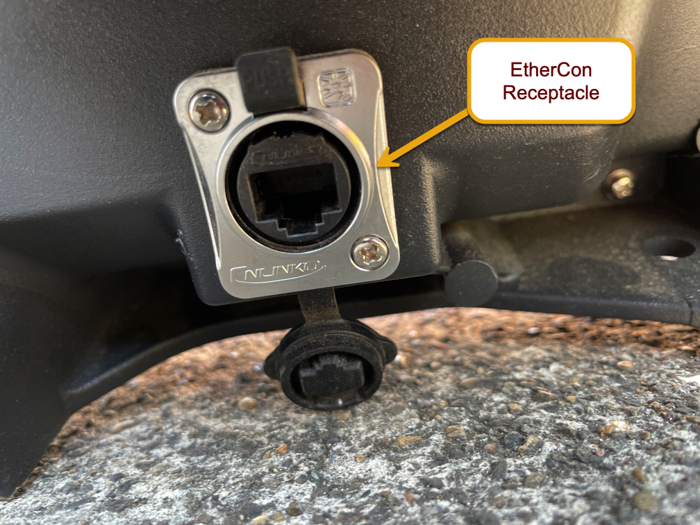
To plug in an EtherCon connector, simply push it into place, ensuring that the connector is properly aligned. To unplug, push the release tab at the top of the receptacle while pulling out on the connector.
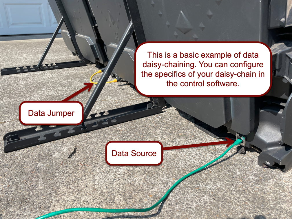
The data connections on the back of the LED screens do not have specific “in” and “out” designations. The control software is smart enough to determine which one is which based on how you have configured the screen in the software. The only thing you must keep in mind is which screen has been designated as the beginning of the daisy-chain and plug the data source into that screen.
If you find that your setup requires a longer run of cable than can be accomplished with Cat-6, NovaStar offers the CVT320 fiber converter. These devices convert the data signal from Cat-6 cable to single-mode fiber optics, and allow for up to a 20km distance between sending unit and receiving unit. CVT320s can be placed between sending card and LED screens, or between two LED screens that have been daisy-chained together. Note that you'll need to order two units—one to convert from Cat-6 to fiber at the transmitting end, and another to convert from fiber back to Cat-6 at the receiving end. More information here.