LED Screen Software Setup NovaLCT ASB Display Board
This article will show you how to configure the control software for LED screens to properly display a scoreboard.
Download and Install NovaLCT
NovaLCT is the control software that will allow you to configure your sending card to properly replicate your computer's display and send it to your LED screens. NovaLCT requires Windows.
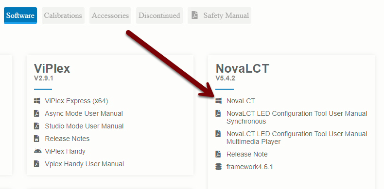
To download the latest version of NovaLCT, visit the NovaStar downloads page, click on the Software heading, and click the NovaLCT link under the NovaLCT heading.
Once the software finishes downloading, extract the installer file from the zip file, and run the installer .exe file.
Follow the prompts to install the software. Once the software itself finishes installing, you will be prompted to install several device drivers which are necessary to communicate with the control hardware. Wait a good fifteen seconds after each driver finishes to ensure there are no more before proceeding.
When prompted, you should choose not to launch NovaLCT at this time (the software is happier if you've already connected a sending card before launching).
Connect the Sending Card
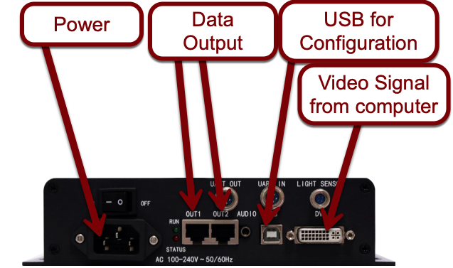
Connect the sending card to power, then connect the USB port on the sending card to an available USB port on the computer where you installed NovaLCT. Connect the DVI port on the sending card to a video output port (HDMI, DVI, VGA, or DisplayPort) using an appropriate cable or adapter. Finally, use a Cat-6 cable of an appropriate length to connect the Out 1 port on the sending card to one of the data ports on the first LED screen in your daisy-chain.
Power the sending card on with the rocker switch, and then start NovaLCT from the desktop icon or Start menu.
Configure the Sending Card
Determine your screen resolution
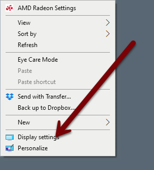
In order to properly map each pixel on your computer's screen to a pixel on the LED screen, you'll need to tell the sending card what resolution your computer screen is running at. To determine this, right click on your Windows desktop background and choose Display Settings.
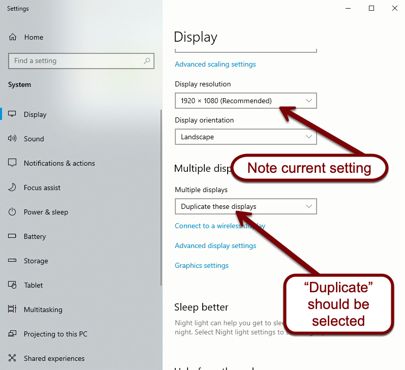
On the Display Settings window, scroll down until you see the Multiple Displays drop-down menu. Ensure that Duplicate these displays is selected, and then note what resolution is selected on the Display resolution drop-down menu.
The final setting we need to check is the refresh rate for your monitors. Click Advanced display settings, and check the refresh rate for the connected screens. From the Select a display... drop-down menu, select Mars Display. Under the Refresh rate drop-down menu, ensure that either 30 Hz, 50 Hz, or 60 Hz is selected (60 Hz is preferred). If another choice is selected (like 59.94 Hz), select one of these three choices instead. Note what setting is selected, and close the Display Settings window.
Access Screen Configuration
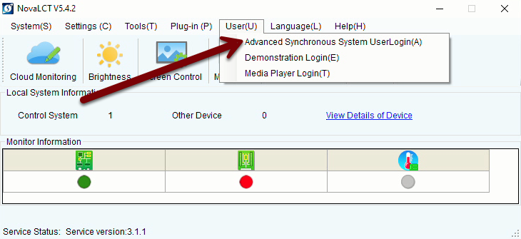
Once NovaLCT launches, navigate to User Advanced Synchronous System UserLogin from the menu bar.
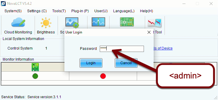
When prompted for a password, enter admin, then select Login.
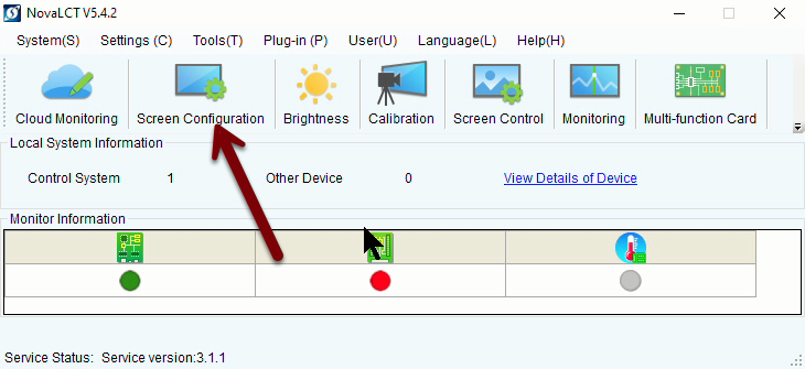
Next, select Screen Configuration from the main screen. This option doesn't appear until you perform the login procedure.
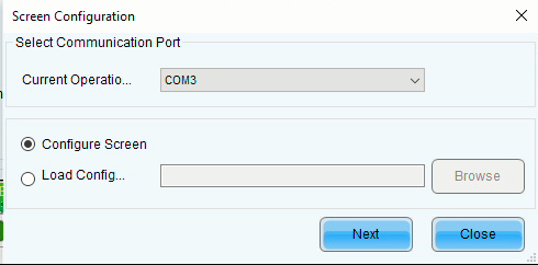
On the subsequent screen, there should only be one choice under Select Communication Port. Ensure that the Configure Screen radio button is selected, and then hit Next.
Set screen resolution
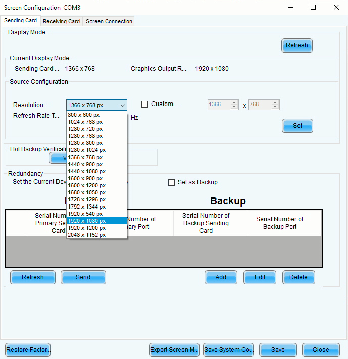
On the main Screen Configuration screen, our first task is to tell the sending card what our screen resolution is. From the Resolution drop-down menu, select the resolution that matches what you noted earlier.
Next, select the refresh rate that you noted from the Windows settings.
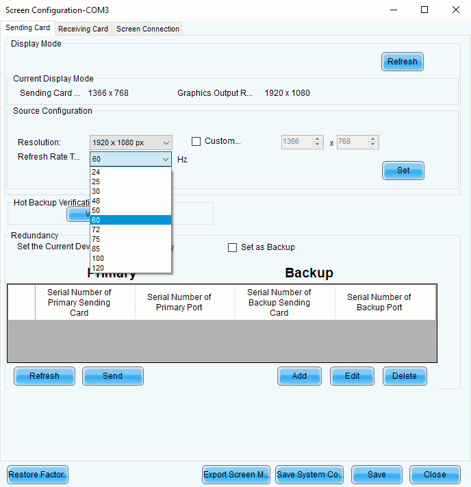
Once you have selected the correct resolution and refresh rate, click Set on the right hand side of the screen.
Set your LED screen connections
After setting your resolution and refresh rate, move to the Screen Connection tab at the top of the screen.
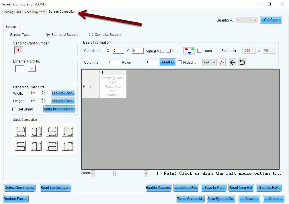
This screen is where you will tell the sending card how the LED screen panels are arranged, what dimensions they are, and how the daisy-chain is configured.
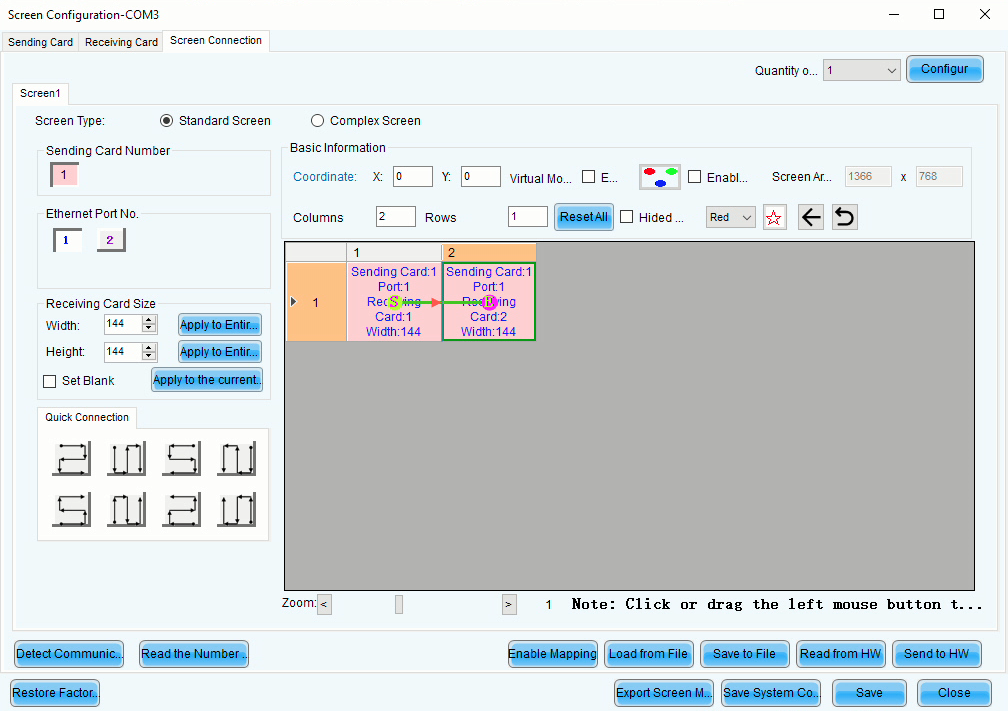
For a simple, two-panel display, enter 2 in the Columns field, and 1 in the Rows field. After pressing <tab> or <enter> to leave the text field, you should see an arrangement like this:
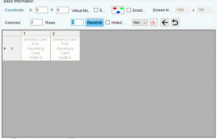
Each of the white squares represents one of your LED screen panels. The gray backdrop represents the overall screen data being fed to the sending card, and the white squares represent what portion of your overall screen will actually be displayed. When the Coordinate fields are set to 0 and 0, the upper-left corner of the table shown represents the upper-left corner of your computer's screen.
Next, move to the Receiving Card Size fields on the left-hand side of the screen. Enter the width and height dimensions (in pixels) of each of your LED screens, then click Apply to Entire Column and Apply to Entire Row. See below for some common LED screen pixel dimensions.
Common LED Cabinet Pixel Dimensions
P8: 120x120
P6 (AKA 6.67): 144x144
P5: 196x196
The final step in configuring your LED screens is to dictate the order of the daisy-chain. Select the output port on the sending card you'd like to run your screen from under Ethernet Port No., then click on each screen in the order you'd like the chain to run in. The S shown on the screen indicates the start of the daisy-chain, and the E indicates the end. Two screens, with the beginning of the daisy-chain on the left as you face them, would look like this:
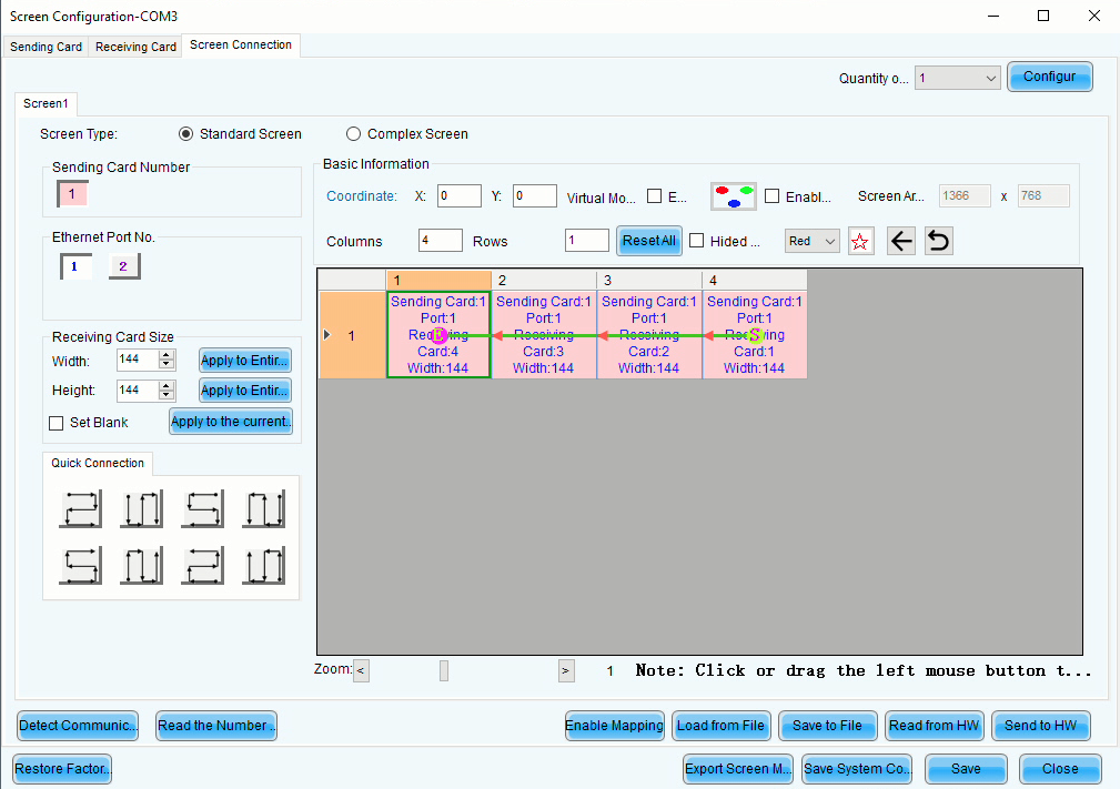
Four screens, with the beginning of the daisy-chain on the right as you face them, would look like this:
If you need to reset your connection settings, click Reset All.
Once you've set up your screen configuration, click Send to HW at the bottom-right of the screen. Once you get a confirmation message that the configuration was successfully saved, click Save, and then click Close.
After these steps, you should confirm that the LED screens are indeed displaying the correct portion of your desktop (i.e., the top-left corner), and then you should proceed to configure your scoreboard software accordingly.